1. [50 points] Given the RF circuit shown below
Por um escritor misterioso
Last updated 01 abril 2025
![1. [50 points] Given the RF circuit shown below](https://media.cheggcdn.com/media/f7d/f7d4ba02-a1e6-4a4f-99d1-d5205de9fa78/phpC21TvI.png)
Answer to 1. [50 points] Given the RF circuit shown below,
![1. [50 points] Given the RF circuit shown below](https://resources.altium.com/sites/default/files/styles/max_width_1300/public/blogs/Stepped%20Impedance%20Transformer%20for%20Complex%20Loads-82344.jpg?itok=YzF6mBDN)
Impedance Transformer for Complex Loads
![1. [50 points] Given the RF circuit shown below](https://www.allaboutcircuits.com/uploads/thumbnails/Figure_5._Circuit_with_corrected_mesh_current_direction_for_I2_.jpg)
Mesh Current Method (Loop Current Method), DC Network Analysis
![1. [50 points] Given the RF circuit shown below](https://haygot.s3.amazonaws.com/questions/1613703_434779893e37427cb3246e7c020035dc.png)
For the circuit shown, with R_{1} = 1.0Omega, R_{2} = 2.0Omega, E_{1} = 2 V and E_{2} = E_{3} = 4 V, the potential difference between the points 'a' and 'b' is approximately (in V).
![1. [50 points] Given the RF circuit shown below](https://img.electronicdesign.com/files/base/ebm/electronicdesign/image/2011/10/electronicdesign_com_sites_electronicdesign.com_files_uploads_2013_01_63946_fig5.png?auto=format,compress&w=500&h=281&cache=0.06035191030992837&fit=max)
Back to Basics: Impedance Matching (Part 1)
![1. [50 points] Given the RF circuit shown below](https://resources.altium.com/sites/default/files/styles/max_width_1300/public/blogs/Quarter-Wave%20Transformer%20Design%20For%20Real%20and%20Reactive%20Loads-82203.jpg?itok=XHr_2oNR)
Quarter-Wave Transformer Design For Real and Reactive Loads
![1. [50 points] Given the RF circuit shown below](https://search-static.byjusweb.com/question-images/toppr_ext/questions/885733_481bac9d20db4fcbb1c08d0545a36939.png)
In the circuit shown in the figure, the input voltage is 20V, VBE=0 and VCE=0. The values of IB,IC and β are given by.
![1. [50 points] Given the RF circuit shown below](https://www.laser.com/dhouston/cm19a-eggbeater.png)
Improve CM19A
![1. [50 points] Given the RF circuit shown below](https://media.cheggcdn.com/media/b7c/b7c593f6-bd38-4217-9108-c8480511d99c/phpJQXYZ8.png)
Solved Problem 1. Consider common emitter amplifier circuit
![1. [50 points] Given the RF circuit shown below](https://media.springernature.com/m685/springer-static/image/art%3A10.1038%2Fs41598-021-91355-4/MediaObjects/41598_2021_91355_Fig1_HTML.png)
Optimum power transfer in RF front end systems using adaptive impedance matching technique
![1. [50 points] Given the RF circuit shown below](https://www.electronics-tutorials.ws/wp-content/uploads/2013/08/opamp15.gif?fit=346%2C219)
Non-inverting Operational Amplifier Configuration
![1. [50 points] Given the RF circuit shown below](https://www.allaboutcircuits.com/uploads/thumbnails/Figure_4._Label_the_voltage_drop_polarities_.jpg)
Solving Unbalanced Wheatstone Bridge Circuits Via Mesh Current Method, DC Network Analysis
Recomendado para você
-
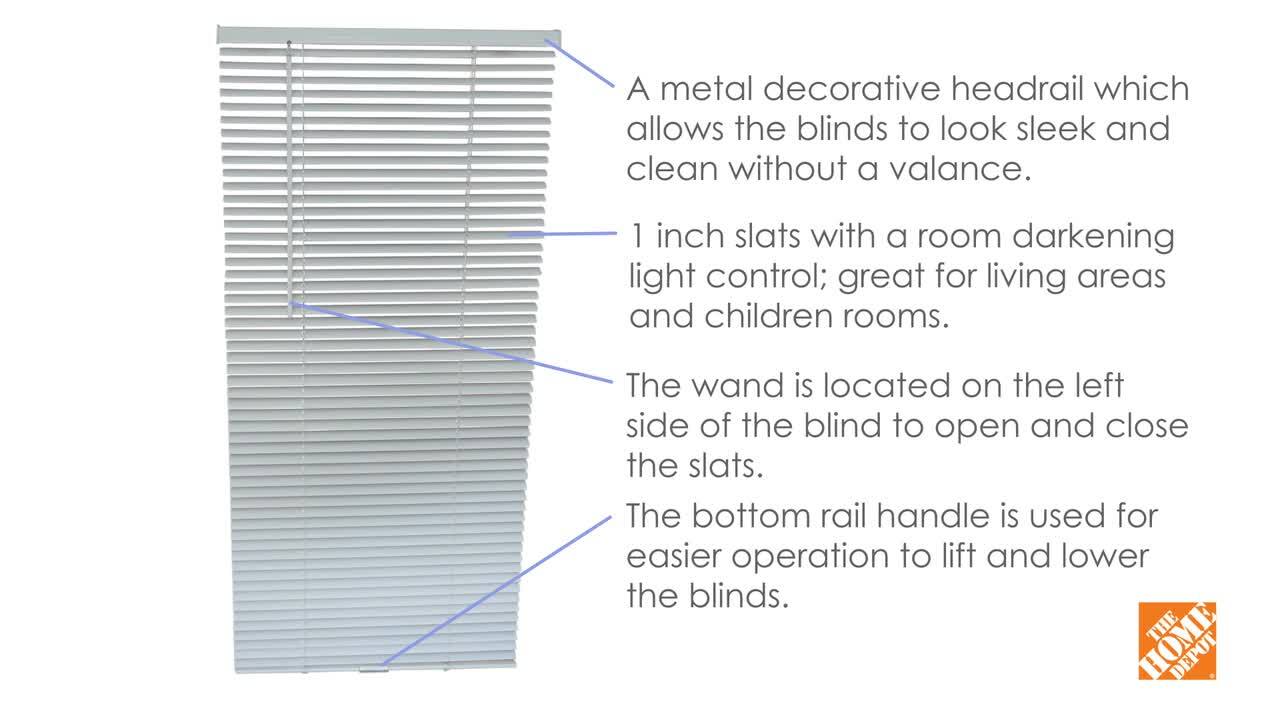 Hampton Bay White Cordless Room Darkening Vinyl Mini Blinds with 1 in. Slats-39 in. W x 72 in. L (Actual Size 38.5 in. W x 72 in. L) 10793478353187 - The Home Depot01 abril 2025
 -
 ryuginx can't open and I've checked settings and there is nothing there. it says application can't be opened. : r/Ryujinx01 abril 2025
 -
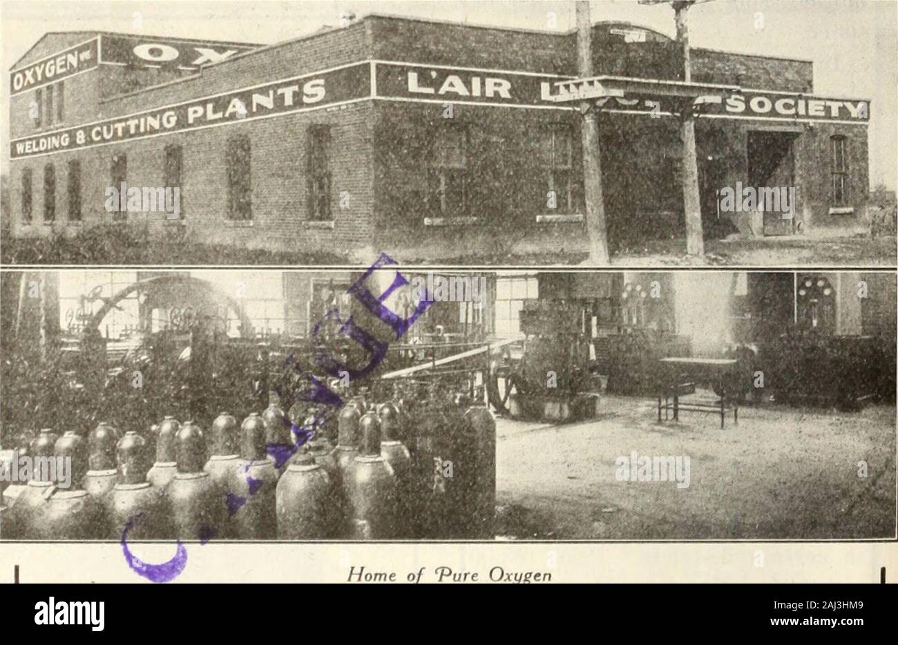 Canadian transportation & distribution management . Ballast PlowRopes WreckingRopes opes SWifch R Derrick Ropes Semap ho r e/ Strands vr MANUFACTURED BY The B. GREENING WIRE CO., Limited Hamilton, Ont. Montreal, Que..01 abril 2025
 -
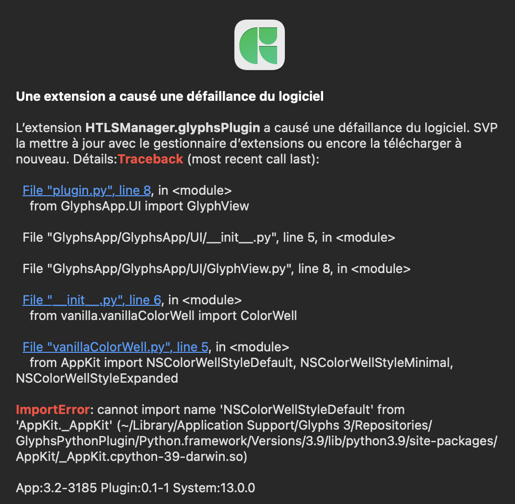 HT Letterspacer does not start + HTLS Manager bug - Glyphs - Glyphs Forum01 abril 2025
 -
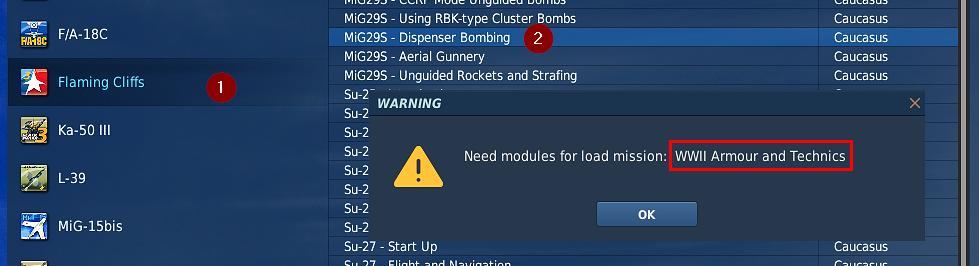 MiG-29S training mission Dispenser Bombing - Flaming Cliffs 3 Bugs & Problems - ED Forums01 abril 2025
 -
 Less popular module this time, but I'll share it anyways, L-39 kneeboards! : r/hoggit01 abril 2025
 -
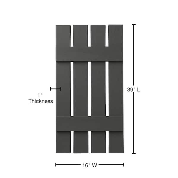 Ply Gem 16 in. x 39 in. Polypropylene 4-Board Open Board and Batten Shutters Pair in Spanish Moss VIN401639 93 - The Home Depot01 abril 2025
 -
 NEW FEH Refines of July 2022 for L!Roy, B!Fjorm, Kjelle, Panne, Mordecai & F!Mareeta! : r/OrderOfHeroes01 abril 2025
 -
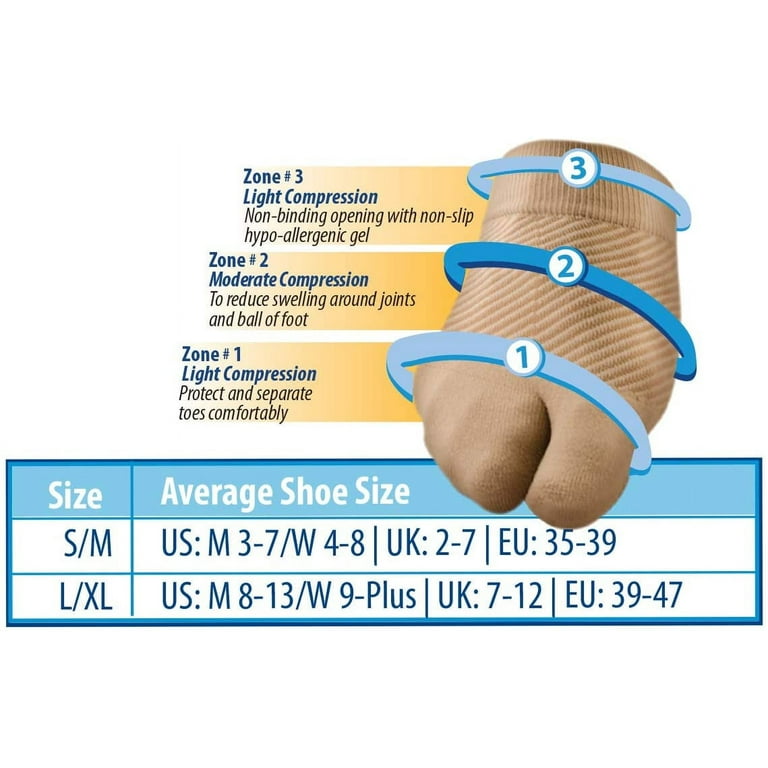 Forefoot Compression Sleeves, Bunion Comforter and Split Toe Alignment Sleeve (Small/Medium)01 abril 2025
 -
 figg Vacuum Compression Storage Bags - M, L and XXL (27 x 19 in to 31 x 39 in)* 6 Pack - Leakproof and Carbon neutral - Vacuum seal bags for01 abril 2025
você pode gostar
-
 Stranger Things 4 part 2: todo lo que sabemos hasta ahora01 abril 2025
 -
Shai Nemesh - Human Resources Director - Wolfoods, Inc.01 abril 2025
-
/origin-imgresizer.eurosport.com/2022/12/20/3512250-71592168-2560-1440.jpg) CFR Cluj, învinsă de Hermannstadt în prelungiri! Echipa lui Petrescu a ratat ocazia de a urca pe locul 1 în SuperLigă - Eurosport01 abril 2025
CFR Cluj, învinsă de Hermannstadt în prelungiri! Echipa lui Petrescu a ratat ocazia de a urca pe locul 1 în SuperLigă - Eurosport01 abril 2025 -
 Top 10 Best Plugins On Roblox. Exactly as the tile says, in this post…, by Molegul01 abril 2025
 -
 Image editor - Free edit tools icons01 abril 2025
 -
![Top 10 Harem Anime With An Overpowered Transfer Student [HD]](https://i.ytimg.com/vi/O7AcjdUUR4U/maxresdefault.jpg) Top 10 Harem Anime With An Overpowered Transfer Student [HD]01 abril 2025
Top 10 Harem Anime With An Overpowered Transfer Student [HD]01 abril 2025 -
 How to Draw Anime Boy Hair Spiky hair edition +PSD File01 abril 2025
 -
 MONCOLLÉ Figure ML-31 Shiny Rayquaza | Authentic Japanese Pokémon Figure | Worldwide delivery from Japan01 abril 2025
 -
 Rangiku Matsumoto Sexy Bleach 111 by michaelxgamingph on DeviantArt01 abril 2025
 -
 Dados Sapo 4k Tv Consola De Jogos De Vídeo Com 2.4g Controlador Sem Fio 10000 Jogos Clássicos Apoio Ps1/gba Retro Jogo Consola Dendy - Consoles De Vídeo Game - AliExpress01 abril 2025
